 |
|||
|
|
|||
|
Page Title:
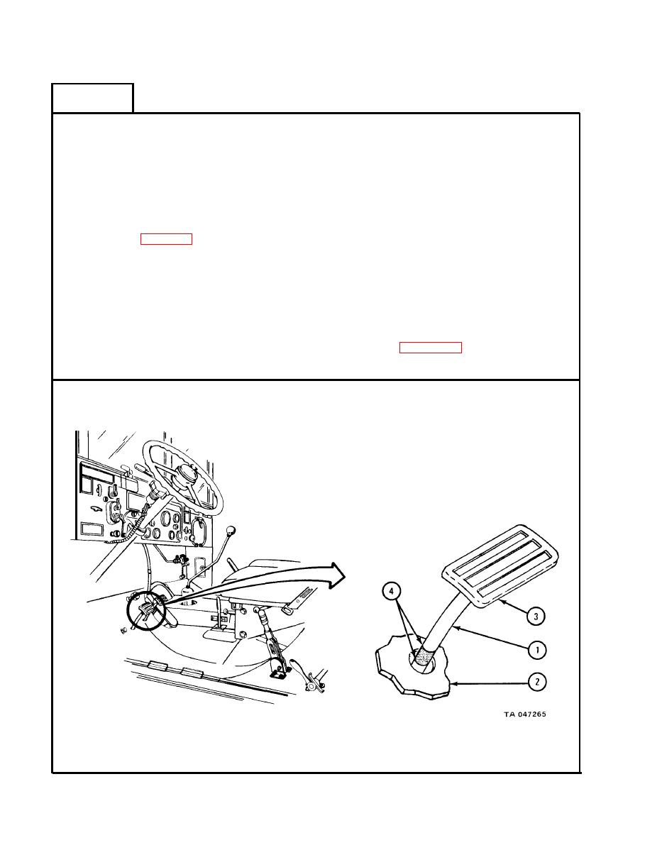
CLUTCH CONTROL AND LINKAGE REMOVAL , REPAIR, REPLACEMENT, AND ADJUSTMENT - continued |
|
||
| ||||||||||
|
|
 TM 9-2320-209-20-3-1
FRAME 8
1.
Using chalk, put mark on clutch pedal shaft (1) where shaft meets floor ( 2).
Using hand, push clutch pedal (3) down until resistance is felt. While still
2.
holding down pedal, put another chalk mark on pedal shaft (1) where shaft
meets floor (2) .
Let go of pedal (3) and measure distance between two marks (4) using a
3.
6-inch ruler. Distance (free pedal travel) should be 1 1/2 to 2 inches.
If free pedal travel is not 1 1/2 to 2 inches, do clutch adjustment procedure.
4.
Refer to para 3-3e.
NOTE
Follow-on Maintenance Action Required:
Tell direct support maintenance to put- power
1.
takeoff on transmission.
2.
Fill transmission with fluid. Refer to
LO 9-2320-209-12/1.
Put on accelerator linkage. Refer to para 4-29.
3.
END OF TASK
3-14
|
|
Privacy Statement - Press Release - Copyright Information. - Contact Us |
