 |
|||
|
|
|||
|
Page Title:
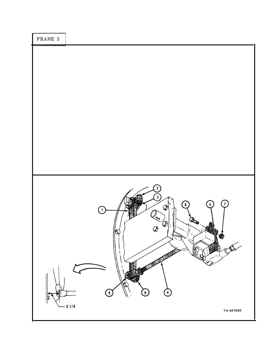
CLUTCH CONTROL AND LINKAGE REMOVAL , REPAIR, REPLACEMENT, AND ADJUSTMENT - continued |
|
||
| ||||||||||
|
|
 TM 9-2320-209-20-3-1
Push lower end of clutch throwout shaft lever (1) forward until resistance is
1.
noted. Using scale, measure distance from center of lever bottom hole to
transmission flange as shown.
NOTE
Measurement should be approximately 3 1/4 inches.
If measurement is not approximately 3 1/4 inches, take off lever (1) and turn
2.
it one spline at a time until measurement is correct.
Using 3/4-inch wrenches, hold bolt (2) and tighten nut (3) .
3.
NOTE
Before joining rod assembly (4) to control lever (5) , put
lever in up position.
Join rod assembly (4) to control lever (5) with bolt (6) and locknut (7) .
4.
Locknut must be on transmission side as shown.
Join rod assemblv (4) to clutch throwout shaft lever (1) using pin (8) . Head
5.
"
o
-
f pin must be on transmission side as shown. Using prybar, pry pin in
clevis ( 9) until head of pin seats against clevis.
Using 3/4-inch wrenches, tighten locknut (7).
6.
Go TO FRAME 4
3-9
|
|
Privacy Statement - Press Release - Copyright Information. - Contact Us |
