 |
|||
|
|
|||
|
|
|||
| ||||||||||
|
|
 TM 3-6665-225-12
Table 3-4. M42 alarm unit troubleshooting table
MALFUNCTION
TEST OR INSPECTION
CORRECTIVE ACTION
1. ALARM-RED INDICATOR AND LOUDSPEAKER INOPERATIVE
Step 1. Position selector switch (8, fig. 1-5) to TEST. If no response, replace batteries (para 3-16).
Step 2. Check for damaged telephone cable wires (para 3-2 d) between M42 alarm unit and M43 detector unit or loose con-
nection at binding posts (7, fig. 1-5).
a. Replace damaged telephone cable.
b. Reconnect loose wires.
2. ALARM-RED INDICATOR FLASHES, BUT LOUDSPEAKER INOPERATIVE
Check that selector switch is positioned to HORN ON.
Position selector switch to HORN ON.
Section IV. M43 DETECTOR UNIT
in chassis assembly.
3-9. General
The operator is authorized to replace a defective
flow rate meter (FLOWMETER), rainshield as-
sembly, detector cell, electronic module, and
pump assembly.
3-10. FLOWMETER
Remove FLOWMETER (3, fig. 1-3) by
unscrewing it (counterclockwise) from handle (2).
Install replacement FLOWMETER by screwing
it (clockwise) into handle.
3-11. RAINSHIELD Assembly
Remove RAINSHIELD assembly (1, fig. 1-3) by
unscrewing it (counterclockwise) from handle (2).
Install replacement RAINSHIELD assembly by
screwing it (clockwise) into handle.
3-12. Detector Cell
a. Removal. Each new detector cell must be
stabilized after installation. Stabilization is
accomplished during startup and operation (para
2-9) .
(1) Release four catches (12, fig. 1-2) from
catches (13) and separate detector assembly (6)
from bottom case assembly (9).
(2) Turn the lobed nut of bail (2, fig. 3-22)
counterclockwise and swing bail away from
detector cell (3).
CAUTION
Do not twist or exert excessive side mo-
tion to detector cell during removal or
detector cell ports may be broken and
left in chassis.
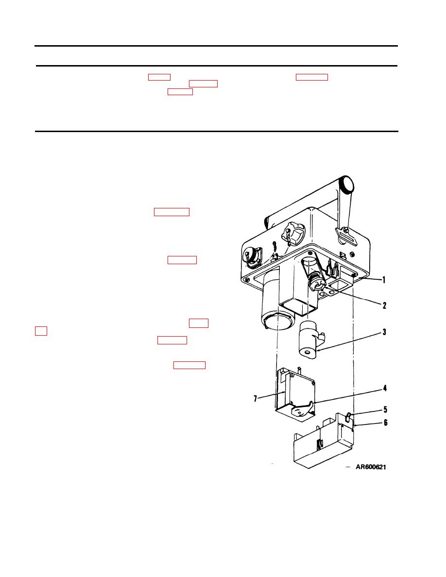
(3) While rocking detector cell (3) gently,
pull it directly from chassis assembly (1).
b. Replacement.
(1) Remove detector cell from its can.
Remove plastic bag, two caps, and plug from
detector cell.
(2) Dampen outside of the two detector cell
1
Chassis asembly
5
Catch
ports with a few drops of water.
2
Bail
6
Pump assembly
(3) Position detector cell (3) so that its ports
3
Detector cell
7
Electronic module
4
Turnlock fastener
are alined with their corresponding fittings in
Figure 3-22. M43 detector unit modular components.
chassis assembly (1). Press detector cell into place
Change 1
3-24
|
|
Privacy Statement - Press Release - Copyright Information. - Contact Us |
