 |
|||
|
|
|||
|
Page Title:
Installing Equipment as a System |
|
||
| ||||||||||
|
|
 TM 3-6665-225-12
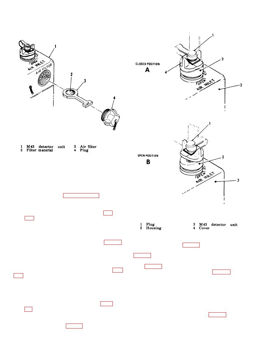
Figure 2-4. Installing air filter.
(5) Install and tighten AIR FILTER plug
(4).
2-8. Installing Equipment as a System
The remaining procedures require that the alarm
system be installed in accordance with the appro-
priate instructions in paragraphs 3-1 and 3-4.
NOTE
Do not connect power to M43 detector
unit 24 VDC INPUT connector (11, fig.
29. Startup and Operation
These procedures start and place the alarm
Figure 2-5, AIR INLET assembly.
system into operation.
unit. M43 detector unit horn (2) and M42 alarm
unit loudspeaker (5, fig. 1-5) must sound.
from AIR OUTLET port. Remove cover (10) from
e. Position M42 alarm unit selector switch (8,
24 VDC INPUT connector (11).
b. Check that AIR INLET assembly is in
from M43 detector unit REMOTE binding post
CLOSED position (fig. 2-5, A). Unscrew plug (1).
(17, fig. 1-2). Adjust M43 detector unit HORN
VOL-BATTERY TEST knob (6, fig. 2-1) for
desired level.
NOTE
f. Press ZERO ADJUST knob (5), rotate it
Notify personnel within audible range
fully counterclockwise, and release it. Horn must
stop sounding and pump assembly must operate.
that alarm system is to be tested.
NOTE
g. Press HORN VOL-BATTERY TEST knob
If any startup tests fail, refer to table
(6). Meter (1) must indicate 24 minimum; release
knob.
mation.
handle (2). Insert and twist FLOWMETER
d. Connect power source connector to 24 VDC
firmly clockwise into top of AIR INLET assembly
INPUT connector (11, fig. 1-2) of M43 detector
2-6
|
|
Privacy Statement - Press Release - Copyright Information. - Contact Us |
