 |
|||
|
|
|||
|
Page Title:
Stowing the Lifting/Locking Assemblies |
|
||
| ||||||||||
|
|
 TM 10-5411-233-13&P
CARGO BED COVER (CBC), TYPE III, 2 1/2 T CARGO TRUCK, LMTV, AND LMTV TRAILER 0005 00
OPERATION UNDER USUAL CONDITIONS
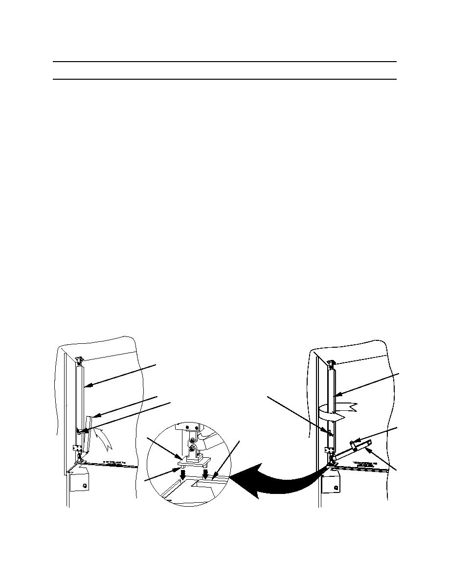
Stowing the Lifting/Locking Assemblies
CAUTION
Be sure that the winch cables do not have any slack prior to releasing
and stowing the four lifting/locking assemblies. If the cables have slack,
move the lever on the ratchet handle to the right and turn the ratchet
handle clockwise SLIGHTLY to raise the upper section of the CBC. Turn
the ratchet handle just enough to take up any slack in the cables. Do not
raise the upper section beyond the warning line on the side wall of the
upper section. Raising the upper section of the CBC beyond the warning
line may cause the cables to snap. Failure to take out the slack in the
winch cables will make it very difficult to release the lifting/locking
assemblies.
Once the lower personnel door panel has been stowed, the four lifting/locking assemblies (1) must be
released from their vertical position and stowed on the underside of the roof.
To release and stow each of the lifting/locking assemblies (1), remove the hairpin cotter (2) that secures
the handle (3) and swing the handle down so that it is approximately perpendicular to the main tube (4) of
the lifting/locking assembly (1). Replace the hairpin cotter (2) in the clevis pin.
While moving the handle (3) slightly up and down as needed, disengage the base plate (5) with
protruding pins (6) from the slots (7) formed by the interlock extrusion.
When the lifting/locking assembly (1) has been released from the slots (7), remove the hairpin cotter (2)
installed in the clevis pin on the main tube (4) and swing the handle (3) up until the hole in the handle clip
(8) slides over the clevis pin. Lock the handle (3) in position by installing the hairpin cotter (2) in the clevis
pin.
1
4
2
3
2
8
5
7
3
6
0005 00-29
|
|
Privacy Statement - Press Release - Copyright Information. - Contact Us |
